


The Two main components
L: Joystick Cradle
R: Tiller Support
In top to bottom order, the clamp system consists of Joystick Cradle, Tiller Support, and the Display Monitor Arm VESA plate (sold separately).
All photos and instructions contained here are based on CAPTAIN side setup. If you purchased the system for First Officer side, everything will be mirrored.
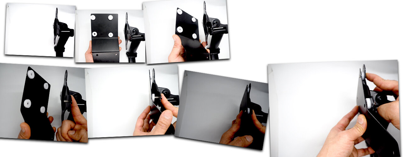
Step One
You are viewing these pictures from what is going to be the front side of the finished setup.
Put together your Display Monitor Arm VESA plate and the Tiller Support as shown.
Insert TWO of the EIGHT M6 Bolts included in the package through the TWO white collars closest to you into the Display Monitor Arm end.
Leave the remaining SIX M6 bolts for now.

Step Two
While Holding the two parts previously put together and the bolts, hold the Joystick Cradle with the other hand and align the TWO M6 holes closest to you on the Joystick Cradle with the TWO bolts from the previous step.
This step is much easier if assisted by another person.

Step Three
Drive the TWO M6 Bolts from previous steps fully into the Joystick Cradle.
Insert and tighten TWO unused M6 bolts in the remaining VESA holes as shown.

Step Four
Install the Display Monitor Arm to the desk.
Slot in a compatible joystick into the Joystick Cradle as shown.

Step Five
Set down the joystick on the Joystick Cradle making sure it is placed laterally symmetrical.
Tighten the two screws at the back of the Joystick Cradle to fix the joystick into the corner holders.

The Last Step
Almost there.
Place your CAT3DESIGN Tiller on the Tiller Support and screw in the remaining FOUR M6 screws fully through the Tiller Support into the base of the tiller unit. If your tiller has anti-vibration pads on the bottom you may remove them for a cleaner fit.
The CAT3DESIGN A320 Landing Gear Lever unit would compliment the setup superbly as shown, allowing you to simulate the real cockpit geometry.